19 October 2024

How to implement water movement in Godot

Japanese landscape we are going to implement
In my previous article, I explained how to create a shader to reflect a scene on the surface of a sprite. However, such a reflection is only possible on an absolutely still sheet of water. Normally, water has surface disturbances that distort that reflection. In this article, we're going to enhance the previous shader so that it shows this distortion and changes over time.

As with other articles, you can find the code for this one in my GitHub repository. I recommend downloading it and opening it locally in your Godot editor to follow along with the explanations, but make sure to download the code from the specific commit I’ve linked to. I’m constantly making changes to the project in the repository, so if you download code from a later commit than the one linked, what you see might differ from what I show here.

I don’t want to repeat explanations, so if you’re not yet familiar with UV coordinates in a Godot shader, I recommend reading the article I linked to at the beginning.

Therefore, we are going to evolve the shader we applied to the rectangle of the water sprite. The code for that shader is in the file Shaders/WaterShader.gdshader.

To parameterize the effect and configure it from the inspector, I have added the following uniform variables:

Shader parameters configurable from the inspector

The wave_strength and wave_speed parameters are intuitive: the first defines the amplitude of the distortion of the reflected image, while the second defines the speed of the distortion movement.

However, the wave_threshold parameter requires some explanation. If you place a mirror at a person’s feet, you expect the reflection of those feet to be in contact with the feet themselves. The reflection is like a shadow—it typically begins from the feet. The problem is that the algorithm we will explore here may distort the image from the very top edge of the reflection, causing it not to be in contact with the lower edge of the reflected image. This can detract from the realism of the effect, so I added the wave_threshold parameter to define at what fraction of the sprite the distortion effect begins to apply. In my example, it’s set to 0.11, which means that the distortion will start at a distance from the top edge of the water sprite equivalent to 11% of its width (i.e., UV.y = 0.11).

Finally, there is the wave_noise parameter. This is an image. For a parameter like this, we could use any kind of image, but for our distortion algorithm, we’re interested in a very specific one—a noise image. A noise image contains random black and white patches. Those who are old enough might remember the image seen on analog TVs when the antenna was broken or had poor reception; in this case, it would be a very similar image. We could search for a noise image online, but fortunately, they are so common that Godot allows us to generate them using a NoiseTexture2D resource.

Configuring the noise image

A configuration like the one shown in the figure will suffice for our case. In fact, I only changed two parameters from the default configuration. I disabled Mipmaps generation because this image won’t be viewed from a distance, and I enabled the Seamless option because, as we will see later, we will traverse the image continuously, and we don’t want noticeable jumps when we reach the edge. Lastly, I configured the noise generation algorithm to FastNoiseLite, though this detail is not crucial.

The usefulness of the noise image will become apparent now, as we dive into the shader code.

To give you an idea of the values to configure for the above variables, I used the following values (I didn’t include in the screenshot the parameters configured in the previous article for the static reflection):

Shader parameter values

Taking the above into account, if we look at the main function of the shader, fragment(), we’ll see that there’s very little difference from the reflection shader.

fragment() shader method

If we compare it to the code from the reflections article, we’ll notice the new addition on line 50: a call to a new method, get_wave_offset(), which returns a two-dimensional vector that is then added to the UV coordinate used to sample (in line 58) the color to reflect.

What’s happening here? Well, the distortion effect of the reflection is achieved not by reflecting the color that corresponds to a specific point but by reflecting a color from a nearby point. What we will do is traverse the noise image. This image has colors ranging from black to pure white; that is, from a value of 0 to 1 (simultaneously in its three channels). For each UV coordinate we want to render for the water rectangle, we’ll sample an equivalent point in the noise image, and the amount of white in that point will be used to offset the sampling of the color to reflect by an equivalent amount in its X and Y coordinates. Since the noise image does not have abrupt changes between black and white, the result is that the offsets will change gradually as we traverse the UV coordinates, which will cause the resulting distortion to change gradually as well.

Let’s review the code for the get_wave_offset() method to better understand the above:

Code for the get_wave_offset() method

The method receives the UV coordinate being rendered and the number of seconds that have passed since the game started as parameters.

Line 42 of the method relates to the wave_threshold parameter we discussed earlier. When rendering the water rectangle from its top edge, we don’t want the distortion to act with full force from that very edge because it could generate noticeable aberrations. Imagine, for example, a person standing at the water’s edge. If the distortion acted with full force from the top edge of the water, the reflection of the person’s feet would appear disconnected from the feet, which would look unnatural. So, line 42 ensures that the distortion gradually increases from 0 until UV.y reaches the wave_threshold, after which the strength remains at 1.

Line 43 samples the noise image using a call to the texture() method. If we were to simply sample using the UV coordinate alone, without considering time or speed, the result would be a reflection with a static distorted image. Let’s assume for a moment that this was the case, and we didn’t take time or speed into account. What would happen is that for each UV coordinate, we would always sample the same point in the noise image, and therefore always get the same distortion vector (for that point). However, by adding time, the sampling point in the noise image changes every time the same UV coordinate is rendered, causing the distortion image to vary over time. With that in mind, the multiplicative factors are easy to understand: wave_speed causes the noise image sampling to change faster, which speeds up the changes in the distorted image; multiplying the resulting distortion vector by wave_strength_by_distance reduces the distortion near the top edge (as we explained earlier); and multiplying by wave_strength increases the amplitude of the distortion by scaling the vector returned by the method.

And that’s it—the vector returned by get_wave_offset() is then used in line 58 of the fragment() method to offset the sampling of the point being reflected in the water. The effect would be like the lower part of this figure:

Our final rendered water movement

13 October 2024

How to implement water reflections in Godot

Our japanese image
I love the simplicity of Godot's shaders. It's amazing how easy it is to apply many of the visual effects that bring a game to life. I've been learning some of those effects and want to practice them in a test scene that combines several of them.

The scene will depict a typical Japanese postcard in pixel art: a cherry blossom tree swaying in the wind, dropping flowers, framed by a starry night with a full moon, Mount Fuji in the background, and a stream of water in the foreground. Besides the movement of the tree, I want to implement effects like falling petals, rain, wind, cloud movement, lightning, and water effects—both in its movement and reflection. In this first article, I’ll cover how to implement the water reflection effect.

The first thing to note is that the source code for this project is in my GitHub repository. The link points to the version of the project that implements the reflection. In future projects, I will tag the commits where the code is included, and those are the commits I’ll link to in the article. As I progress with the articles, I might tweak earlier code, so it's important to download the commit I link to, ensuring you see the same code discussed in the article.

I recommend downloading the project and opening it in Godot so you can see how I’ve set up the scene. You’ll see I’ve layered 2D Sprites in the following Z-Index order:

  1. Starry sky
  2. Moon
  3. Mount Fuji
  4. Large black cloud
  5. Medium gray cloud
  6. Small cloud
  7. Grass
  8. Tree
  9. Water
  10. Grass occluder

Remember that sprites with a lower Z-Index are drawn before those with a higher one, allowing the latter to cover the former.

The grass occluder is a kind of patch I use to cover part of the water sprite so that its rectangular shape isn’t noticeable. We’ll explore why I used it later.

Water Configuration

Let's focus on the water. Its Sprite2D (Water) is just a white rectangle. I moved and resized it to occupy the entire lower third of the image. To keep the scene more organized, I placed it in its own layer (Layer 6) by setting both its "Visibility Layer" and "Light Mask" in the CanvasItem configuration.

In that same CanvasItem section, I set its Z-Index to 1000 to ensure it appears above all the other sprites in the scene, except for the occluder. This makes sense not only from an artistic point of view, as the water is in the foreground, but also because the technique we’ll explore only reflects images of objects with a Z-Index lower than the shader node's. We’ll see why in a moment.

Lastly, I assigned a ShaderMaterial based on a GDShader to the water’s "Material" property.

Let’s check out the code for that shader.

Water Reflection Shader

This shader is in the file Shaders/WaterShader.gdshader in the repository. As the scene is 2D, it's a canvas_item shader.

It provides the following parameters to the outside:

Shader Uniforms
Shader variables we offer to the inspector

All of these can be set from the inspector, except for screen_texture:

Shader Inspector
Shader Inspector

Remember, as I’ve mentioned in previous articles, a uniform Sampler2D with the hint_screen_texture attribute is treated as a texture that constantly updates with the image drawn on the screen. This allows us to access the colors present on the screen and replicate them in the water reflection.

This shader doesn’t distort the image; it only manipulates the colors, so it only has a fragment() component:

Fragment Method
fragment() method

As seen in the previous code, the shader operates in three steps.

The first step (line 33) calculates which point on the screen image is reflected at the point of water the shader is rendering.

Once we know which point to reflect, the screen image is displayed at that point to get its color (line 38).

Finally, the reflected color is blended with the desired water color to produce the final color to display when rendering. Remember, in GDShader, the color stored in the COLOR variable will be the one displayed for the pixel being rendered.

We’ve seen the second step (line 38) in other shaders in previous articles. It's basically like using the eyedropper tool in Photoshop or GIMP: it picks the color of a specific point on an image. Keep in mind that, when the shader executes, the image consists only of the sprites drawn up to that point. That is, sprites with a Z-Index lower than the one with our shader. This makes sense: you can’t sample a color from the screen that hasn’t been drawn yet. If objects are missing from the reflection, it’s likely because their Z-Index is higher than the shader node’s.

Now, let’s see how to calculate the screen coordinate to reflect:

get_mirrored_coordinate() Method
get_mirrored_coordinate() method

This method tests your understanding of the different coordinate types used in a 2D shader.

In 2D, you have two types of coordinates:

UV coordinates: These have X and Y components, both ranging from 0 to 1. In the rectangle of the water sprite that we want to render with our shader, the origin of the coordinates is the top-left corner of the rectangle. X increases to the right, and Y increases downward. The bottom-right corner of the water rectangle corresponds to the coordinate limit (1, 1).

SCREEN_UV coordinates: These are oriented the same way as UV coordinates, but the origin is in the top-left corner of the screen, and the coordinate limit is at the bottom-right corner of the screen.

Note that when the water sprite is fully displayed on the screen, the UV coordinates span a subset of the SCREEN_UV coordinates.

To better understand how the two types of UV coordinates work, refer to the following diagram:

UV Coordinate Types
UV coordinate types

The diagram schematically represents the scene we’re working with. The red area represents the image displayed on the screen, which in our case includes the sky, clouds, moon, mountain, tree, grass, and water. The blue rectangle represents the water, specifically the rectangular sprite where we’re applying the shader.

Both coordinate systems start in the top-left corner. The SCREEN_UV system starts in the screen’s top-left corner, while the UV system starts in the top-left corner of the sprite being rendered. In both cases, the end of the coordinate system (1, 1) is in the bottom-right corner of the screen and the sprite, respectively. These are normalized coordinates, meaning we always work within the range of 0 to 1, regardless of the element’s actual size.

To explain how to calculate the reflection, I’ve included a blue triangle to represent Mount Fuji. The red area is the mountain itself, while the triangle in the blue area represents its reflection.

Suppose our shader is rendering the coordinate (0.66, 0.66), as represented in the diagram (please note, the measurements are approximate). The shader doesn’t know what color to show for the reflection, so it needs to sample the color from a point in the red area. But which point?

Calculating the X-coordinate of the reflected point is easy because it’s the same as the reflection point: 0.66.

The trick lies in the Y-coordinate. If the reflection point is at UV.Y = 0.66, it means it's 1 - 0.66 = 0.33 away from the bottom edge (rounded to two decimal places for clarity). In our case, where the image to be reflected is above and its reflection appears below, the natural expectation is that the image will appear vertically inverted. Therefore, if the reflection point was 0.33 away from the bottom edge of the rectangle, the reflected point will be 0.33 away from the top edge of the screen. Thus, the Y-coordinate of the reflected point will be 0.33. This is precisely the calculation done in line 11 of the get_mirrored_coordinate() method.

So, as the shader scans the rectangle from left to right and top to bottom to render its points, it samples the screen from left to right and bottom to top (note the difference) to acquire the colors to reflect.

This process has two side effects to consider.

The first is that if the reflection surface (our shader’s rectangle) has less vertical height than the reflected surface (the screen), as in our case, the reflection will be a "squashed" version of the original image. You can see what I mean in the image at the start of the article. In our case, this isn’t a problem; it’s even desirable as it gives more depth, mimicking the effect you'd see if the water’s surface were longitudinal to our line of sight.

The second side effect is that, as we scan the screen to sample the reflected colors, there will come a point where we sample the lower third of the screen where the water rectangle itself is located. An interesting phenomenon will occur: What will happen when the reflection shader starts sampling pixels where it’s rendering the reflection? In the best case, the color sampled will be black because we’re trying to sample pixels that haven’t been painted yet (that’s precisely the job of our shader). So what will be reflected is a black blotch. To avoid this, we must ensure that our sampling doesn’t dip below the screen height where the water rectangle begins.

Using our example from the image at the beginning of the article, we can estimate that the water rectangle occupies the lower third of the screen. Therefore, sampling should only take place between SCREEN_UV.Y = 0 and SCREEN_UV.Y = 0.66. To achieve this, I use line 13 of get_mirrored_coordinate(). This mix() method allows you to obtain the value of its third parameter within a range defined by the first two. For example, mix(0, 0.66, 0.5) would point to the midpoint between 0 and 0.66, giving a result of 0.33.

By limiting the vertical range of the pixels to sample for reflection, we ensure that only the part of the screen we care about is reflected.

With all this in place, we now have the screen coordinate that we need to sample in order to get the color to reflect in the pixel our shader is rendering (line 15 of get_mirrored_coordinate()).

This coordinate will then be used in line 38 of the fragment() method to sample the screen.

Once the color from that point on the screen is obtained, we could directly assign it to the COLOR property of the pixel being rendered by our shader. However, this would create a reflection with colors that are exactly the same as the reflected object, which is not very realistic. Typically, a reflective surface will overlay a certain tint on the reflected colors, due to dirt on the surface or the surface's own color. In our case, we will assume the water is blue, so we need to blend a certain amount of blue into the reflected colors. This is handled by the get_resulting_water_color() method, which is called from line 40 of the main fragment() method.

get_resulting_water_color() Method
get_resulting_water_color() method

The main effect of this method is that the water becomes more blue as you get closer to the bottom edge of the water rectangle. Conversely, the closer you are to the top edge, the more the original reflected colors should dominate. For this reason, the mix() method is used in line 29 of get_resulting_water_color(). The higher the third parameter (water_color_mix), the closer the resulting color will be to the second parameter (water_color, set in the inspector). If the third parameter is zero, mix() will return the first parameter's color (highlighted_color).

From this basic behavior, there are a couple of additional considerations. In many implementations, UV.Y is used as the third parameter of mix(). However, I chose to add the option to configure a limit on the maximum intensity of the water's color. This is done in lines 25-28 using the clamp() method. This method will return the value of currentUV.y as long as it falls within the range limited by 0.0 and water_color_intensity. If the value is below the lower limit, the method returns 0.0, and if it exceeds the upper limit, it will return the value of water_color_intensity. Since the result of clamp() is passed to mix(), this ensures that the third parameter's value will never exceed the limit set in the inspector, via the uniform water_color_intensity.

Another consideration is that I’ve added a brightness boost for the reflected images. This is done between lines 20 and 22. I’ve configured a uniform called mirrored_colors_intensity to define this boost in the inspector. In line 22, this value is used to increase the three color components of the reflected color, which in practice increases the brightness of the color. In line 22, I also ensure that the resulting value does not exceed the color limits, although this check may be redundant.

The Occluder

Remember that we mentioned this shader can only reflect sprites that were drawn before the shader itself. In other words, it can only reflect sprites with a lower Z-Index than the shader. Since we want to reflect all sprites (even partially the grass sprite), this means the water rectangle needs to be placed above all other elements.

If we simply place the water rectangle above everything else, the result would look like this:

Water without occluder

It would look odd for the shoreline to be perfectly straight. That’s why I’ve added an occluder.

An occluder is a sprite fragment that acts like a patch to cover something. It usually shares the color of the element it overlaps so that they appear to be a single piece. In my case, I’ve used the following occluder:

Occluder
Occluder

The occluder I used has the same color as the grass, so when placed over the lower part of the grass, it doesn't look like two separate pieces. On the other hand, by covering the top edge of the water rectangle, it makes the shoreline more irregular, giving it a more natural appearance.

The result is the image that opened this article, which I will reproduce here again to show the final result in detail:

Water with occluder
Water with occluder

With this, I conclude this article. In a future article, I will cover how to implement some movement in the water to bring it to life.


01 September 2024

"Creating an RTS Game in Unity 2023" by Bruno Cicanci

Book cover
In any learning process, there comes a point where you surpass the initial level and from there, you enter the intermediate stage. There are still many things you don't know, but you find that the available bibliography drastically reduces. There are many books to introduce you to the world of game development, but not as many for the intermediate-advanced level.

I started this book because the table of contents promised to cover topics not commonly found in other books on Unity, such as level creation, tool development through editor extension, multiple unit selection, formations, resource management, fog of war, or customizing builds. However, I had my reservations, given my past experiences with PacktPub books.

Fortunately, this book has proven to be above average compared to others from the same publisher. It indeed covers those topics and more, in a thorough and clear manner, using expressive and high-quality source code. I could tell that the author is a good developer and knows what they're doing. Thanks to this, I’ve learned a few new things along the way—things I didn't know and that will now enrich my way of developing in Unity. At this stage, that's no small feat.

To illustrate everything, the book develops a real-time strategy game, akin to War of Warcraft, with a top-down perspective. As you might imagine, it’s all done with free resources and in a mock-up mode, but I have to admit it touches on many aspects that should be considered in a game of that genre.

If I had to point out one downside, there was one feature I was particularly interested in, the fog of war, and I was disappointed that one of the elements used to implement it was a legacy feature. It’s impossible to guarantee that a technical book will remain up-to-date after a few years, but recognizing yourself, in your book, that you're going to use a legacy feature... I find that quite disappointing. Everything explained in a technical book should be current at the time of its writing.

Aside from that small detail, the truth is that it’s a recommendable book from which you can learn a lot. Highly recommended.

31 August 2024

How to implement a level map with two level of Fog Of War (Two level FOW) in Godot

Map with two level FOW
In my previous article, I explained how to implement a level map in Godot with fog of war. That map initially appeared black, but it gradually revealed itself as the character moved through it. It was a single-level map because, once the character traversed an area, that area remained fully uncovered, and all enemies passing through it were visible, even if the main character was far away.

Other games implement a two-level FOW, where the area immediately surrounding the character, within their line of sight, is fully uncovered, and enemies passing through it are entirely visible, while in areas left behind, only the static part of the map is visible, but not the enemies that might be there. Generally, maps with two-level FOW display distant areas with a dimmer tone, where only the static part is visible, to distinguish them from areas where enemies might appear.

It turns out that, when you have a map with one level of FOW, implementing a second level is incredibly easy. So I will pick up from where we left off at the end of the previous article. If you haven’t read it yet, it is essential that you do so, using the link at the beginning of this one if you like. To avoid repetition, I will assume that everything discussed in that article is understood.

You can find all the code for this article in its GitHub repository.

Starting from that map, we need to consider that the shader we used for the map (Assets/Shaders/Map.gdshader) checked each pixel of the map’s image to see if that same pixel was colored in the mask map rendered by SubViewportMask. If it wasn’t colored on the mask map, it assumed that the pixel was not visible and painted it black instead of painting it with the color coming from the map’s SubViewport (remember that the map's TextureRect was connected to the image rendered by SubViewportMap). Conceptually, the mask map corresponds to the areas already explored.

In this new map, we want to take it a step further by distinguishing the explored areas (the mask map) from the directly visible areas. The former will be shown in a dimmer tone, displaying only the static part, while the latter will continue to be rendered as before.

What are the directly visible areas? Those are on the shapes map. They are rendered in SubViewportShapes with a camera that only captures the white circle placed on the character. So far, we had used the shapes map for the mask shader (Assets/Shaders/MapMask.gdshader), but now we will also use it in the map shader to know which pixels of the map are in the player’s visible area.

Once we know how to distinguish, within the explored areas, which ones are in the visible zones and which ones are not, we need to render an image that only shows the visible part of the map. As in the other cases, this can be achieved with a SubViewport. In my case, I simply copied SubViewportMap and its child camera. I called the copy SubViewportStatic.

SubViewportStatic

To ensure that this SubViewport only shows the static part, the Cull Mask of its camera needs to be configured to capture only layer 1, where I placed all the static elements of the environment.

Screenshot of the camera inspector

Note that the same camera in SubViewportMap is configured to capture layers 1 and 4 (1 for the static objects in the environment and 4 for the character's identifying icons placed on them).

To make the image captured by the camera dimmer, you need to assign it an Environment resource (in the field with the same name). Once you’ve created this resource, you can click on it to configure it. In the Adjustments section, I enabled it and lowered the default brightness to half.

Environment configuration of the camera

Notice that the Environment resource has many more sections, so imagine the number of things you could do to the image captured by the camera.

With that, we now have a dimmer image of the environment, but without characters. Just the static part we needed. The map shader will receive this image through a Uniform (Static Map Texture), which we’ll configure through the inspector to point to SubViewportStatic.

Map shader inspector


Under the hood, the shader code is very similar to that of the previous article.

New shader code

The main novelty is the new uniform we mentioned earlier (line 12) to receive the image of the static elements map, and lines 16 to 18. If the code reaches this point, it means that line 14 concluded that since the pixel was marked with color in the mask map, it corresponds to an already explored area. In line 16, it checks if that pixel, besides being in an explored area, corresponds to a colored pixel in the shapes map (i.e., the directly visible areas). If not, the pixel receives the color of the equivalent pixel in the static map image (line 17). If the pixel was indeed colored in the shapes map (and its red channel was different from 0), that pixel would receive the default color coming from SubViewportMap (which shows the enemy icons).

The result is the image that opens this article, with the area surrounding the character showing the closest enemies, the more distant explored areas displaying only the static elements of the environment, and the unexplored areas colored in black.

27 August 2024

How to implement a level map with Fog Of War (FOW) in Godot

In games that offer a level map, it’s common to cover the areas that the player has not yet explored. As the player progresses through the terrain, those sections of the map are gradually revealed. This is known as the Fog of War (FOW), and starting from this simple concept, things can get quite complex. A common enhancement is to give the player a limited vision range, so the revealed areas of the map only show other players or NPCs if they are within the player’s vision range. Outside of this range, the map only displays static elements of the environment: buildings, rivers, forests, mountains, etc. Another refinement is to apply the fog of war not only to the map but also to the 3D level environment.

In this article, I will explain the simplest approach. We will uncover the map, and the revealed areas will retain full visibility even if the player moves away from them. Once we understand the basics, we’ll see that it’s not that difficult to apply more sophisticated techniques.

The elements I refer to in this article are available in my DungeonRPG repository. This is the code I developed while following GameDevTV’s course "Godot 4 C# Action Adventure: Build your own 2.5D RPG," which I highly recommend. The course doesn’t cover maps or FOW, but the mini-game it implements provides an excellent foundation for learning how to create them.

Map Creation

I won’t delve into this here because I already explained it in the article on how to create a minimap. Creating a complete map is similar. You just need to ensure that the orthographic camera is positioned at the center of the environment (from above) and has a size (parameter Camera3D > Size) large enough to cover the entire environment. The Subviewport that the Camera3D projects to must cover the entire screen.

You’ll only need a scene with the following structure:

When placing the scene in the environment, you’ll need to position the camera in the appropriate spot. The problem is that you won’t have direct access to it since it’s in its own scene. I solved this by having the root node’s script in the scene use the [Tool] attribute for the main class. This attribute allows the script to execute logic while being manipulated within the editor.

The script placed at the root of the scene is located at Scripts/General/Map.cs. Its source code is in Godot C# (as is all the code I develop), but I don’t think developers who prefer GDScript will have any trouble understanding it. Specifically, being marked with the [Tool] attribute, its _Process() method executes continuously in the editor as long as there’s a node with that script in the hierarchy. The content of that method is as follows:


The Engine.IsEditorHint() method returns true when the calling code is executed from the editor. It’s very useful for defining code that should run while working in the editor but not when running the game.

In this case, two things are done: it looks for a Marker3D to obtain its position, and that position is used to place the Camera3D node of the map.

The Marker3D should be placed as a child of the scene when instantiated in the environment. It’s similar to instantiating a CollisionShape as a child of a CharacterBody3D.


What the GetCameraPositionMarker() method does is check if the scene has any Marker3D as a child. If the user hasn’t configured a Marker3D as a child of the scene, Godot typically shows a warning with a yellow icon.

The decision whether to show that warning is made by the UpdateConfigurationWarnings() method, which is called on line 59 of the last code snippet. This method is built into Godot, and to make its decision, it relies on the information passed in the implementation of the _GetConfigurationWarnings() method, which is an abstract method that classes inheriting from Godot nodes can implement. In my case, I implemented it as follows:

This method is very simple. It returns an array of warning messages. If the array is empty, UpdateConfigurationWarnings() interprets that everything is fine and no warning messages need to be displayed. But if the array contains any strings, it shows the warning icon with the message included in the array.

In my case, I simply check if _cameraPosition is still null (line 87) after the GetNodeOrNull() call on line 58 of GetCameraPositionMarker(). If it turns out to be null (line 87), it indicates that the user hasn’t placed a Marker3D as a child of the scene, so an error message is added to the returned message.

A Marker3D is just a Node3D with a noticeable appearance. It’s great for marking places within the environment that your objects can use as references. The idea in this case is to place the Marker3D at the point in the environment where we want to position the map’s camera (usually the center of the level).

Once you have the Marker3D, the _Process() method calls the UpdateCameraConfiguration() method (from line 80) to configure the camera’s position.

That method updates the configuration of two cameras, the map camera and the visibility zone camera (shapes), which we’ll see shortly. The Marker3D position is used to configure the map camera’s position, while its size and aspect ratio (lines 66 and 67) are configured based on what you’ve set in the inspector via exported fields:

In my case, I created an InputAction so that when the "M" key is pressed, the screen is covered with the map, and it disappears as soon as the key is released:


The rest of the GUI elements subscribe to the MapShown (line 106) and MapHidden (line 110) signals to know when they should hide or reappear.

The Visibility Zones Map

The previous map is the full level map—the one we would offer the player if they could see it from the beginning of the game.

But we’ve decided that the player should not have infinite visibility, but rather be able to see up to a certain distance. This distance is usually modeled as a circle around the player, with the radius being the player’s maximum vision range.

What we’re going to do is hide the map behind a black layer, the fog of war (FOW), and only open holes in the fog where the player’s vision circle passes. To do this, we’ll use the mask concept we used in the minimap article. In that case, we used a circle image to define that the visible part of the minimap was circular. In this case, I used a similar technique by creating a dynamic image with a black background, where anything white defines the visible areas of the map.

To create this dynamic image, I used a similar approach to the character icons in the minimap. I placed a circular sprite above the main character and assigned that sprite to layer 5.


This layer is exclusively for FOW. Neither the game camera nor the minimap camera includes layer 5 in their culling mask, so the circle will be invisible to them. However, the camera I added to its own Subviewport in the FOW map scene does include this layer.


As shown in the figure, that camera only sees the white circles on layer 5, and the rest will be colored black, which is the background color I configured. The result is that the Subviewport will render a black screen with a white circle moving around.

Besides the mentioned layer and background color, it’s important that both the map Subviewport (SubViewPortMap in the figure) and the visibility zones Subviewport (SubViewPortShapes), as well as their respective cameras, have the same configuration so that they have the same scale and cover the same area of the environment, perfectly overlapping.

Configuring a Dynamic Mask

At this point, we have a map and a dynamic image with a white circle that moves with the character. If we wanted to reveal only the area around the player, we would already have most of the elements needed to take the final step. But we want to make things a bit more complex, as we want the character to leave a trail as they move, making the map visible along that trail. Therefore, it is necessary for the vision circle to leave a trace.

This function will be carried out by one more Subviewport (SubViewportMask in the last figure), which will house a fully black ColorRect. The image rendered by this Subviewport will be used to cover the map, acting as the FOW. The peculiarity is that this ColorRect has its own shader:


This shader is located in Assets/Shaders/MapMask.gdshader and is quite simple.


The topic of shaders could fill entire books, but I’ll try to give a very basic introduction. Using Godot’s terminology, this shader "exports" two variables by marking them with the term "uniform": shapesTexture and prev_frame_text. The value of the first one is set through the inspector, and the second is marked with a special attribute (hint_screen_texture), which marks that variable so that Godot automatically assigns it a value with the data from the last image rendered by the Subviewport that is  the parent of the shader node (in this case, SubViewPortMask).

The fragment() method of a shader runs for each pixel on the screen (you know which pixel thanks to the UV and SCREEN_UV variables), and depending on the pixel you’re at, you can modify the color that will eventually be rendered for that pixel using the COLOR variable. By default, the fragment() method runs on a screen with no previous data, so if you want to consider the previous image, you must mark a uniform variable with the attribute (hint_screen_texture) and ensure that the Subviewport of the shader does not clear itself each frame by setting its Clear Mode to Never.


I set the Update Mode to Always so that the calculations we’re about to see are performed even if the map is not visible, ensuring that when the player decides to view it, it is up to date.

If we continue with the MapMask shader, we see that I took the value of the pixel in the visibility zones map (shapesTexture, to which I assigned a reference to SubViewportShapes in the inspector), as well as the value of the pixel in the previous frame (previousColor).

The visibility zones map only has two colors, the black background and the white vision circles, so as soon as the visibility zone pixel is not black, we know it’s a map pixel that should be made visible, so we mark it as white by setting its COLOR to that value (line 10 of the shader). To check if the pixel is different from 0, I simply look at the red channel. Since the circles I used are white, I’m sure the red channel will also be affected as they pass, as that color has components in all three channels. If the visibility zone pixel is black, it means it’s a part of the map that is not within the vision range at this moment, but it could have been in previous moments, so since we want to leave a trail of visible areas, we leave that pixel with the value it had in the previous frame (line 12).

The effect of this shader will be that the character’s vision circle behaves like a brush, drawing white over a black background to mark the character’s trail.

The Final View

Now we need to combine the dynamic mask and the map to display the result somewhere. This will be the role of the TextureRect Map, which I placed as low as possible in the scene hierarchy to ensure it is drawn over all other elements, covering them.

For this TextureRect to read the map’s information, I made its Texture property reference the SubViewportMap. If we did nothing else, this would make the TextureRect faithfully reproduce what SubViewportMap renders.

But we want to incorporate the dynamic mask information, which is why this TextureRect has its own shader, which you can find in Assets/Shaders/MapMask.gdshader.

This shader achieves the desired effect in just a few lines:


In this case, two variables are exported, both configurable through the inspector. In maskTexture, I left a reference to SubViewportMask (the dynamic mask). Meanwhile, in fogColor, I left the color we want to use for areas covered by the FOW.

The shader checks the value of the pixel from the dynamic texture in the same position as the pixel being rendered. If the dynamic mask pixel (maskSample) is black, then I render the final image pixel in black. Here, I check only the red channel again since my masks are white, so I know they have presence in the red channel. If the mask pixel is not black, it means that pixel should be visible, so we don’t do anything and let it render the color from SubViewportMap.

Conclusion

The result is the image at the beginning of this article: a map with FOW that expands its visible areas as the player moves through the environment.

As I mentioned at the beginning of the article, this is the most basic case of FOW. I want to try in a future article the option of a two-level FOW map, where the completely unexplored areas are hidden, and the explored areas only show static elements outside the character’s vision range. This evolution should be straightforward to achieve, but I don’t want to include it in this article to keep it from getting too long.

As for applying FOW to the 3D environment and not just the map, that’s something I’m still trying to understand how to do. As soon as I figure it out, I’ll reflect it in an article here.

I hope you found this interesting.

08 August 2024

How to test multiplayer games in Unity

I am taking the GameDevTV course on multiplayer game development with Unity. When I finish it, I will share my opinion, as I have done with other courses. Until then, I wanted to tell you about a new trick I discovered in Unity: how to create multiple instances of a multiplayer game to test it on one PC.

Having this capability is essential during the development phase to ensure that we synchronize all game elements correctly between different participants. Godot natively includes the ability to run up to 4 independent instances of the game for testing. However, Unity has not had this feature, at least until now.

The course I am taking, for example, limits testing to compiling and running one instance of the game outside the editor (with the "Build and Run" option) and running a second instance within the Unity editor. It doesn’t explain how to test with more than two players, which has not been easy. Searching the internet, I concluded that the closest thing Unity had to Godot’s functionality was a third-party extension called ParrelSync.

The news is that Unity 6 will finally include the feature that Godot users have already enjoyed. Although there is no stable version of Unity 6 yet, you can already test everything in the Preview versions available for installation from Unity Hub.

The functionality is called Multiplayer Play Mode and allows you to simulate up to 4 players: one from the editor and three other virtual instances of the game.

To install it, we need to go to the Package Manager in the Unity 6 editor and install the Multiplayer Play Mode package from the Unity Registry.

To activate a virtual instance of the game, you need to go to Window > Multiplayer Play Mode and select how many instances you want to launch.

Those instances you select will start a boot process, and once they become active, their respective windows will appear. Don’t worry about the long startup time. It only takes that long the first time. After that, the information is cached, and subsequent startups are much faster.

From that moment on, every time we start the game from the editor, it will play in both the editor and the virtual instances, allowing us to simulate the behavior of independent players.

To operate as one of the players, simply select the window of its instance and interact with the game as the player would.

To stop the game, do so from the editor as you would with a single-player game. This will stop the game in all virtual instances.

To make the windows disappear, just deselect them in the Multiplayer Play Mode window.

With this, we have everything we need to test any multiplayer game.

I hope you found this interesting.

19 July 2024

Course "Unity C# Mobile Game Development: Make 3 Games From Scratch" by GameDevTV

The course I took on game development in Godot for mobile platforms left me wanting more. So I decided to take the equivalent course for Unity and compare the two platforms. Specifically, I chose another course from GameDevTV: "Unity C# Mobile Game Development: Make 3 Games From Scratch." In this case, I bought it on Udemy, where I already have other courses.

It is based on developing three projects: a sort of Angry Birds, a racing game, and an Asteroids game. All are very simple but cover the basics: physics configuration, camera handling, and a lot, really a lot, of UI configuration.

  • Regarding mobile-specific topics, the course explains:
  • Editor setup to simulate mobile platforms.
  • Compilation for Android and iOS.
  • Input management through touchscreens, including multi-touch inputs.
  • Notifications.
  • Ads.
  • In-app purchases.

Overall, it's good, but there are several points where it clearly needs an update. The most glaring issue is that the instructor himself acknowledges some of these points. For example, when it comes to Ads, Unity offers two options. The instructor admits that the classic option is already obsolete and that Unity's development is moving towards the second option, but guess which one he explains in the end? Exactly, the one he acknowledged as obsolete.

There are also several moments when Unity has evolved, and the components used in the class either do not appear or do not behave exactly as shown. When that happens and you get stuck, I recommend checking the comments section of the particular class. You'll see it's full of students asking questions, but the instructor never responds. Even so, it must be acknowledged that GameDevTV assigns associate instructors to answer questions, although, in most cases, their answers don't provide much help. In the end, the best tips come from other students' comments. I have also left some contributions, hoping they help someone.

As a platform, Unity is much more mature for making games and monetizing them on mobile platforms than Godot. It is evident that they have components for everything, although I did miss the greater clarity of Godot and, above all, its faster development speed. It drives me crazy every time I modify a Unity script, switch to the editor to test it, and have to spend 5 or 6 seconds staring at the screen while Unity does one of its famous "domain reloads." In comparison, the workflow in Godot is much more agile, with practically instant executions (even using C#), so it doesn't feel as tedious. In my opinion, if you want to make a mobile game intending to profit from ads or in-app purchases, Unity is the best option, although I wouldn't rule out Godot for prototyping, much less for PC games (for which I believe Godot is very well-suited).

In conclusion: the course is good and worth it. It allowed me to solidify concepts, some of which the Godot course had already introduced to me, and it finally helped me understand how to configure UIs in Unity (it's hard to believe, but I hadn't quite grasped it until now). However, be aware that some content is outdated and won't work as expected. So, if you get stuck, it's best to check the comments section because you might discover that the issue isn't your code. With that caveat in mind, I think it's a course that can be very beneficial.


12 July 2024

Course "Master Mobile Game Development with Godot 4: From Concept to App Stores" by GameDev.TV

I'm continuing with the courses included in the latest Humble Bundle pack that I bought, which features courses from GameDev.TV. This time, I'm taking the "Master Mobile Game Development with Godot 4: From Concept to App Stores" course. You can find it on both GameDev.TV and Udemy. Buying the course on one platform or the other will depend on your preferences and which one offers a better discount at a given time. In the end, the course is exactly the same.   

It is focused on game programming for Android or iOS mobile platforms.

The course is supposed to be at an intermediate level, although the first two sections of lessons, where you build a very basic platform game without touching a mobile device, work very well as an introduction (or a refresher, if that's your case) to all the 2D aspects of Godot.

The third section dives into the more specific parts of the course and explains how to set up Godot to generate installable packages for Android and iOS. Regarding mobile gameplay, it covers how to use the device's accelerometer and how to detect and correct screen scaling issues.

I found the fourth and fifth sections quite tedious because they focus on setting up the entire UI and adding functionality to the menu buttons. It's useful if you haven't seen this topic for Godot before, but if you're already familiar with it, these two sections can feel long. Even so, I don't recommend skipping them because what follows relies heavily on the UI set up in this part.

The sixth section is the most interesting because it focuses on how to interact with the Google Play API to offer in-game purchases. It uses Godot's official plugin for this. This section is quite complex and has a couple of points that are not well explained, not due to negligence on the author's part, but because these issues seem to only occur when using Google Play for the first time. Once resolved, they don't happen again, and you forget about them. Since the author has already worked on several Google Play projects, he didn't encounter these issues, and his lesson proceeds smoothly, not realizing that first-timers might face more difficulties. For example, the explanation on how to register as a developer on Google Play seemed brief. There's also a lesson, 6.12 "Acknowledging," where there's an entire thread of comments from people who faced the same issue, without the author stepping in to help. After much searching online, I managed to solve my problem and shared my solution in the comments. The solution was to unlock developer mode, not on the mobile device (which is explained in the course), but in the Play Store app itself. I suspect the author didn't mention this because it's something you unlock at the beginning and then forget about... until you face the issue again. In an introductory course like this, it's a mistake not to mention it.

The seventh section is about publishing the application, but compared to everything else, it is very simple.

The author uses GDScript, but I was translating it to Godot C# on the fly without any issues until the in-game purchases part, which forced me to practice how to call a component in GDScript (the plugin) from C#. Nothing complex. Once you realize that it's about loading the plugin as a GodotObject and then calling its internal methods with the Call() method, everything becomes very straightforward. You just have to keep in mind that the plugin returns Godot's own types, like Array or Dictionary, which are not exactly the same as C#'s native types. In this case, I had to analyze the plugin's source code (in Java) to understand it. For the author, all these type issues were transparent due to GDScript's dynamic typing.

The author explains things well. He is Turkish, but his English is one of the clearest I've heard in a course, and if listening to English is a problem for you, there are subtitles, which are quite accurate based on the few times I've needed to use them. I also found the author's programming practices to be "healthy," resulting in a well-structured program. The principle of "downstream you call methods on references, while upstream you return signals" is something I had already suspected from my own experience, but this is the first time I've heard it explicitly mentioned, and it's a design principle I liked a lot.

Overall, despite its small flaws, the course is generally good and interesting. I recommend it.

08 June 2024

How to implement health bars for characters in Godot games

It is very common for game characters to have progress bars, at their feet or above their heads, to show how much life they have left. 

Godot has two ideal nodes for this: ProgressBar and TextureProgressBar. The first one has everything we might need for a basic bar. The second node is an evolution of the first, allowing for a more attractive visual appearance using textures instead of plain colors. In this tutorial, we will focus on ProgressBar; once you control this, using the TextureProgressBar node is relatively simple.

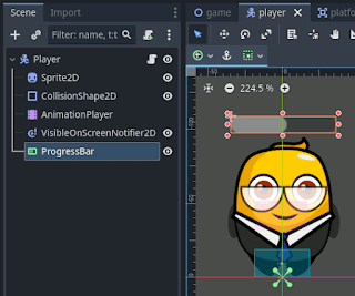
In Godot2D, adding a progress bar to your character is very simple. Just add the ProgressBar node to the character's scene hierarchy and then resize and position the bar using its visual handles.


From there, you only need to configure the visual appearance of the bar and implement its script, as we will see later.

However, adding a life bar to a 3D game character is not so straightforward. The problem is that ProgressBar is a 2D node and cannot be directly added to a 3D game. In fact, if you try to add the node to a 3D game character, as we did with the 2D case, you will see that the scene editor switches to the 2D tab and does not allow you to place the node as part of your 3D scene.

The trick is to use a node we already used in the article about minimaps in Godot: the SubViewport node. This node creates an independent viewing area in a region of the screen. In the case of minimaps, we used it to show the top-down camera's view, while the rest of the screen continued showing what the main camera saw. In this case, the node's role will be to display a 2D element in a region of a 3D game screen.

For minimaps, the trick worked by making the Camera3D node a child of the SubViewport and placing this in the desired screen region using a SubViewportContainer node.

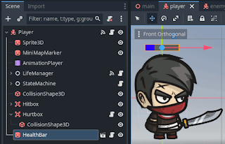
For life bars, it's done similarly: you place the ProgressBar node as a child of the SubViewport, but in this case, you can't use the SubViewportContainer node because it places things in a specific screen position and not relatively to a character, so they move with it through the scene. For this, we can use a Sprite3D node. This node can be positioned relatively to a character, as part of its scene hierarchy. So, we will make the SubViewport and ProgressBar nodes children of the Sprite3D.


Once finished, the life bar will still not be visible. This is because we need to configure the Sprite3D to show the life bar. In other words, we need to configure the Sprite3D to display the image rendered by the SubViewport. To do this, find the Texture property of the Sprite3D in the inspector. When you find it, it will be empty, so you need to create a New ViewportTexture in it and select our SubViewport in the popup window that appears. From that moment on, the bar will be visible within our character's scene.


Normally, beyond tinkering for testing, you will want to concentrate all the bar nodes in their own scene, so you can reuse it for different characters. That’s what I did and what is shown in the previous screenshot.

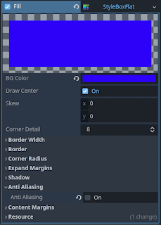
That’s the hardest part of configuring life bars. The next step is to configure the visual appearance of the bar. We will set its size using the Size property of the SubViewport. I usually disable the Show Percentage property of the ProgressBar to not show the percentage. As for the bar colors, we need to look for the Themes Overrides section in the ProgressBar inspector. There, we need to expand another section called Styles. It has two parts: Background and Fill. The first is for defining the visual appearance of the bar’s background, and the second for the main bar. The simplest way is to assign those properties with StyleBoxFlat resources and edit their BG Color property with the desired colors. For example, we could set the background BG Color to a color with Alpha 0, making it completely transparent, and the bar color to blue.


What remains is the logic to update the bar’s values as the character's values change.

The three basic properties of a ProgressBar are: MaxValue, MinValue, and Value. The first two are usually set at the beginning, for example in the _Ready() method, and define the maximum and minimum values the bar will cover. Meanwhile, the Value property is the one we will update throughout the game to make the ProgressBar update the bar length based on the Value relative to the minimum and maximum.

An approach I often follow is to create a C# script for the Sprite3D, with a reference to the ProgressBar:


From that reference, I create properties for the maximum, minimum, and current values, so when these values are modified from outside the script, their equivalents in the ProgressBar are also updated. For example, for the maximum value:


The properties for the minimum and current values are almost identical.

I exported these properties to set initial values from the inspector. For the configured inspector values to apply to the progress bar at the beginning of the game, we will use the _Ready() method:


Once the game starts, the properties will update the ProgressBar as the reference to it will no longer be null.

The remaining task is to provide a means to update the CurrentValue property and, with it, the bar. You can do this in many ways, for example, by having scripts that will update the bar hold a reference to the bar script and manipulate the CurrentValue property through it. This is a valid approach but increases coupling by requiring a direct reference between objects.

Another option, reducing coupling, is to make scripts that modify the life level emit signals (Godot's version of events) whenever a change occurs and have the bar subscribe to these signals. In my example, I followed this approach and included a handler in the bar script to respond to such signals:


Then, I subscribed that handler to the signal emitted by the character whenever it takes damage:


In my example, the damage signal is emitted by the CharacterLifeManager.cs script, which defines the signal as follows:


The previous signal is emitted from line 46 of the ApplyDamage() method of the aforementioned script, which is called whenever the character takes a hit from its opponents:


Using deltas, instead of absolute values, in the OnCurrentValueChanged() handler allows subscribing it not only to damage signals (which transmit negative deltas) but also to healing signals (whose deltas are positive). In this case, the script that manages healing, when the player picks up a potion, emits a signal with a positive delta to which we can subscribe just as we did with the damage signal:


The definition and launch of the signal are very similar to the damage signal, so I won't go over it here.

By relying on signals, we have reduced coupling between components and achieved a highly reusable bar that we can apply to any game element as long as it emits signals with the increment value (whether positive or negative) whenever a monitored value changes. This way, we can reuse this life bar we implemented here with other components to display values that don’t have to be life, such as ammo, karma, or armor level.

This concludes the article; I hope you liked it. If the explanations and screenshots were not enough, you can download the example project I used from my DungeonRPG repository on GitHub. I used as a base the mini-game I made following the GameDevTV course "Godot 4 C# Action Adventure: Build your own 2.5D RPG," which I highly recommend. The course does not cover life bars, but the mini-game it implements is an excellent base for learning how to create them.